
How do you build the world’s smallest construction scaffold from DNA?
In order to build the tip complex, the T3SS has a needle filament that is thought to act as a construction scaffold. This puts 5 tip protein subunits into the correct arrangement for them to self-assemble. To create the tip complex artificially, we’re building the world’s smallest construction scaffolds from DNA. These were designed to mimic the T3SS needle filament that could be chemically functionalised with 5 protein binding sites with the correct spatial arrangement.
The linear scaffold is a 50 base pair length single-stranded DNA template. Primarily used in Blitz, it contains three different ‘domains’ with which function is changed. The 5 prime end is modified with biotin for attachment to a streptavidin surface. A central binding domain consisting of 10 base pairs allows attachment to a complementary modified strand in the middle of the template. The modification was chosen depending on the test used, such as a 5 prime Tris Aminated modification for protein to DNA conjugation. 20 base pairs either side are non-complementary to any other strands, and are thus termed non-binding.
NUPACK algorithim; Nucleic acid sequence design via efficient ensemble defect optimization was utilised in designing a ‘tennis racquet’ like flat DNA design. The racquet was ordered such that the 5’ end was biotinylated, allowing for conjugation to a streptavidin surface. Ten base pair single stranded DNA (ssDNA) was ordered with complementary sequence to the binding domain. This ten base pair ssDNA is the conjugating strand and was made with to be 5’ or 3’ Tris Aminated. (Check out Conjugation Chemistry to find out more). Here’s our NUPACK code!
material = dna
structure tennisracket = D20(U62)
domain stem = N20
domain binding = CCGTCCTGCC
domain nonbinding = TT
tennisracket.seq = stem nonbinding binding nonbinding binding nonbinding binding nonbinding binding nonbinding binding nonbinding stem*
This scaffold was primarily used in understanding binding kinetics! You can check this out here.
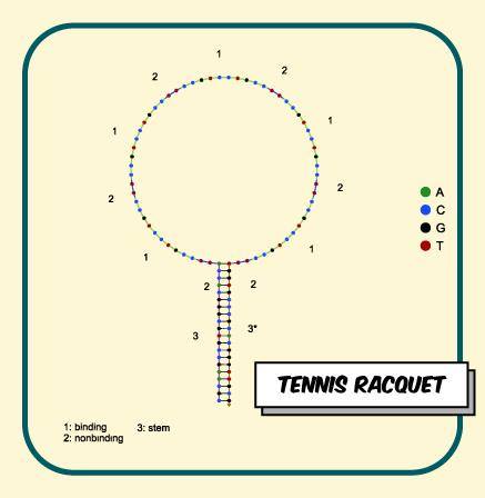
Figure 1. Tennis Racquet design
DNA barrels have previously been made with single walls. We designed barrels with a puckered wall to appropriate the structure’s end to the size required by the tip complex.
Initially, staple crossovers and potential crossover sites for each barrel were designed using an algorithm by our team. Our problem poses a significant design challenge, as the T3SS tip complex has an odd numbered rotational symmetry. Puckered walls allow both odd numbered rotational symmetry, but also smaller diameters, which is perfect for our miniscule tip complex!
The hanging M13 scaffold (of which approximately 180 base pairs exists) was made to hang from the centre of a beta barrel. It was placed here to position it in the most unlikely location for interaction with either end of the barrel.
Here’s what the barrel should look like from one of its ends:
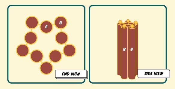
Figure 2. Different views of puckered barrel
CaDNAno was used to draw out the crossovers for our puckered design and thread them over the M13 scaffold strand. Once all staples for the body of the barrel had been drawn out with the correct crossovers, our staple ends were designed.
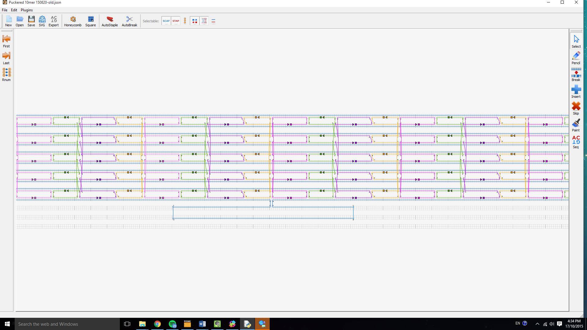
Figure 3: Our puckered DNA barrel design drawn out in CaDNAno
We designed "adaptor" oligos to replace the very end staples of each helix which have a 'staple' domain that is complimentry to M13 and one of two different 'conjugation' domains are complimentary to the our protein conjugation modified oligos. By synthesizing our barrel with different sets of adaptor oligos our design allows the creation of two different scaffold diameters and two different conjugation orientations (Figure 4)
Alpha barrel direct: Inner helicies, outward oriented conjugcation points
Alpha barrel folded: Inner helicies, inward oriented conjugcation points
Beta barrel direct: Outer helicies, outward oriented conjugcation points
Beta barrel folded: Outer helicies, inward oriented conjugcation points
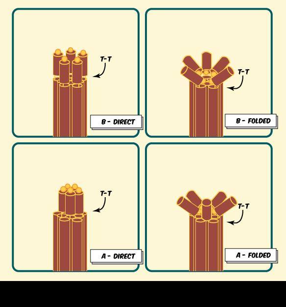
Figure 4: Schematic of the four different arrangments of conjugation chemistries possible using different adaptor sets.
This was our first indication that our design was on track because it showed that our staple and scaffold strands were binding to each other! This was indicated because of the clear difference between m13 and staple only lanes in comparison to full DNA origami mixed lanes (Figure 7)!!
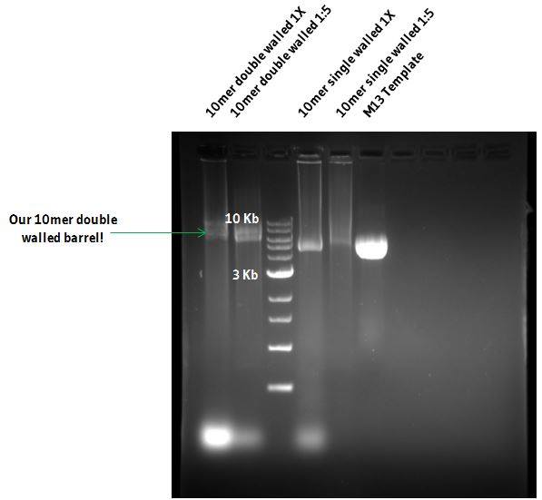
Figure 7: 0.75% agarose gel of Puckered and Unpuckered DNA barrels and M13 scaffold DNA
To make sure our DNA had formed the right shape, we visualised these with AFM (Figure 6) and TEM (Figure 7). These two methods allowed us to clearly see our tiny construction scaffold, which had dimensions that were consistent with our design: Approximately 210nm long.
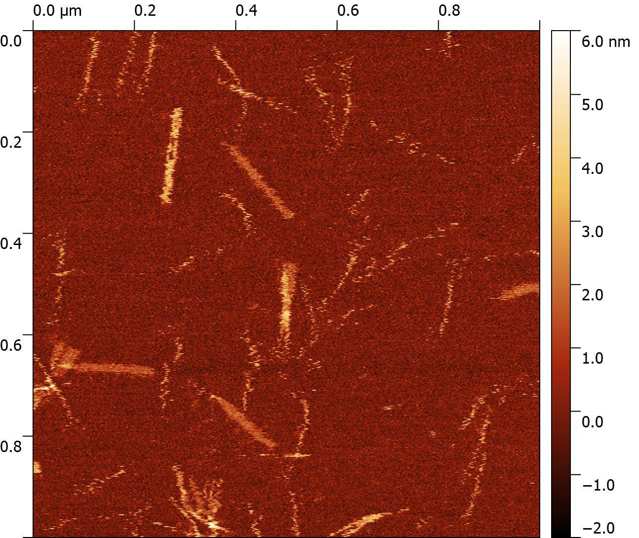
Figure 6: AFM image of "Hero Barrels"
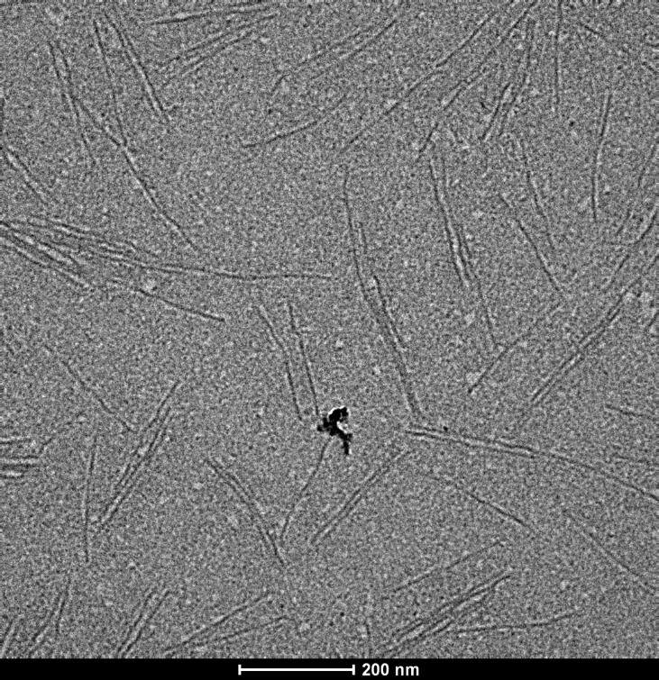
Figure 7: EM image of "Hero Barrels"
AFM and EM only let us see our nanostructures when they’re stuck to a surface. Occasionally the surface itself and the AFM tip can also affect the nanostructures’ shape, which may be why our barrels looked slightly flat with AFM. It was important for us to know whether our structures were round barrels in solution. In order for us to obtain this data, we took our nanostructure to the Australian Synchrotron, where we were able to characterise our DNA nanostructures with Small-Angle X-ray Scattering (SAXS).
By comparing our experimental scattering data with an array of structural models, each with different diameters (Figure 8), we were able to estimate the dimensions of our DNA nanostructure in solution. These were consistent with our design, but the fit to our X-ray scattering data is far from perfect. This could be for several reasons. Firstly, the DNA in solution will not be a static rigid structure like our structural models. Secondly, our sample may not have been 100% pure during our SAXS measurements. Both would flatten the pronounced diffraction bumps compared to those seen in an idealized theoretical scattering pattern (Figure 9).
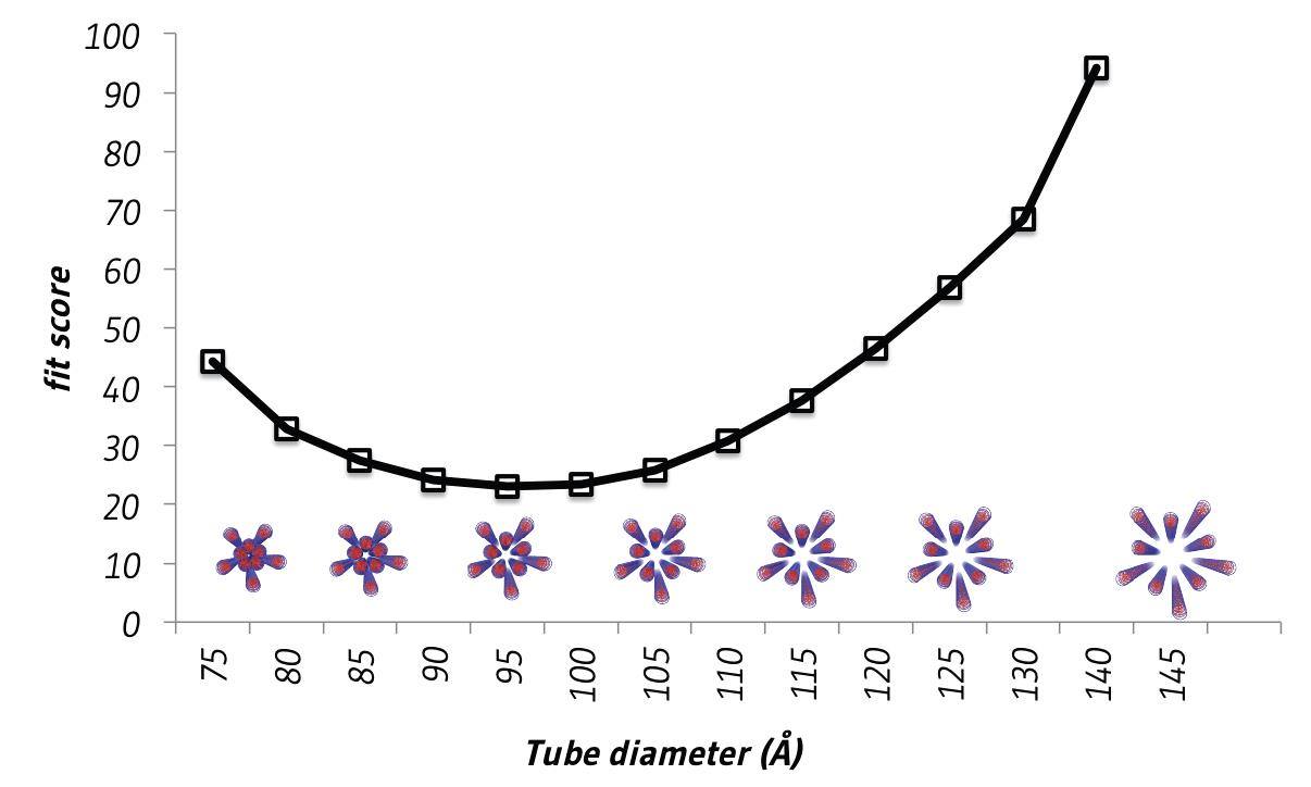
Figure 8: Plot showing fit between theoretical models with various diameters and experimental small-angle X-ray scattering data.
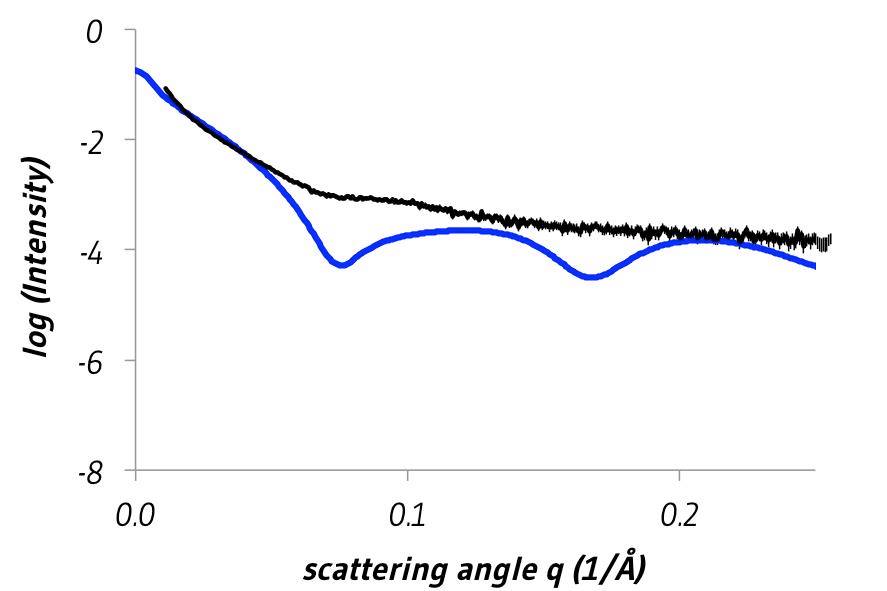
Figure 9: Comparison of theoretical scattering calculated from a structural model of the DNA nanostructure with a diameter of 9.5 nm (blue) and experimental small-angle X-ray scattering (black). Errors are twice the standard error of the mean.
We've designed 2 DNA Scaffolds for assembling the T3SS Needle Tip Complex acording to the specificaitons layed out in our Bioblueprint, and demonstrated that they are of the correct dimentions required, using AFM, EM, and SAXS!!
Following successful design of the barrel and the tennis racquet we aimed to design new scaffolds that could alleviate other issues with isolating complex protein structures. Two particular methods come to mind, and both were aimed at scaffolding the T3SS tip complex. The first design idea was of a designing a pentagonal tessellating surface, which would create a surface with which many tips could form on one DNA origami scaffold.
Pentagons don't tesselate well in two dimentions! So for our second and perhaps more ambitious design we considered 3D shapes that have some petameric symmetry such as dodecahedrons, which are made of pentagons and have 5 fold symmetry on each face, and icosahedrons which have five fold symmetry around their verticies. We used vHelix to design a DNA icosahedron (Figure 10) that, modified with protein conjugation sites surrounding each vertex, would allow the assembly of 12 T3SS tip complex (Figure 11) for each DNA scaffold. Value!
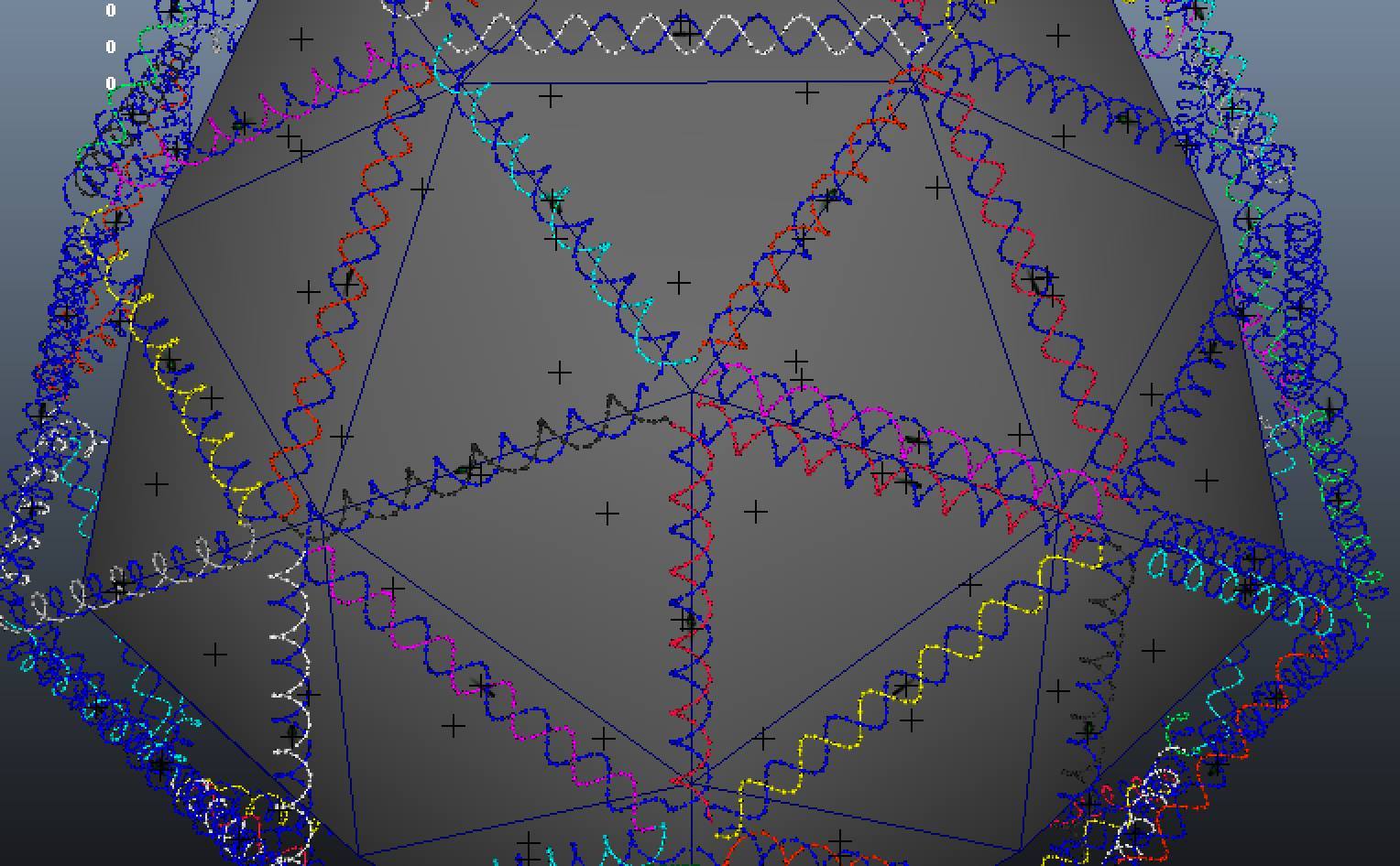
Figure 10: vHelix design of a DNA Icosahedron
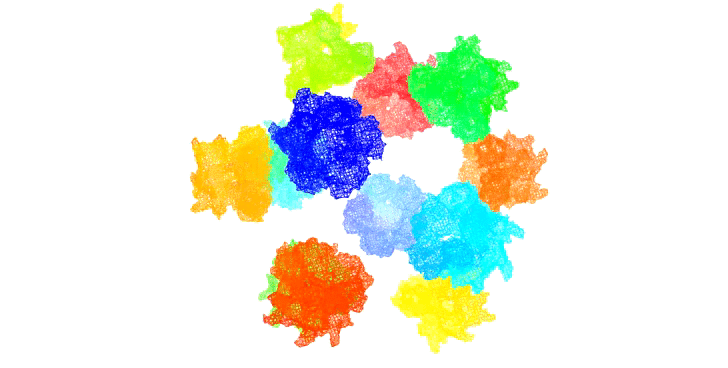
Figure 11: Rendition of T3SS needle tip complexes assembed on an icosahedral scaffold
Resuspension (COMMON staple mix)
DNA was ordered in 3 x 96 well plates. As each well was ordered with dried DNA, we resuspended each well with Synthesis Buffer (SB). Each plate was spun at 23,000 G for 15 minutes prior to resuspension. Synthesis Buffer was first made up to a stock solution of 1 Litre with MQ water. 20 μL of SB was added to each well. Plates were then re-spun.
Synthesis buffer stock solution
SB contains 33 mM Tris Acetate and 12.5 mM Mg Acetate. Stock solutions of Tris Acetate were at 1 M, and the molar weight of Mg Acetate is 142.392 g/mol. We added 33 mL of Tris Acetate and 1.78 grams of Mg Acetate, and added MQ up to 1 L. a 200 mL solution was taken as working SB and used for each experiment.
Making COMMON and STAPLE EXTENSION mixes
The Barrel was ordered with COMMON staples that made the majority of the barrel, and were the first 216 staples. The rest were labelled STAPLE extension DNA staples and were made as mentioned before. 1 μL of each common staple well was added to one Eppendorf tube, to form a COMMON staple mix! Each staple concentration was made to 500 μM with SB. Staple extension mixes were also made for each staple type (labelled with colours in the .csv). Each stock solution of both COMMON and EXTENSIONS were made into 10 μL aliquots, ready for synthesis later on.
M13 Buffer Exchange
The M13mp18 ssDNA template scaffold was purchased from Bayou Biolabs and buffer exchanged with DNA origami synthesis buffer (33mM Tris Acetate, 12.5mM Mg Acetate, pH 8.2) in Micro Bio-Spin™ 6 columns (Bio-Rad). Staple strands were purchased from Integrated DNA Technologies, shipped dry and suspended in DNA origami synthesis buffer to 500µM.
Mixing Stock Solutions
Each aliquot was made to allow 1 to 1 addition of each part required for synthesis. For our common (Non-Hero Barrel) or our stock standard, we used 4 parts. The most important requirement for DNA origami is the M13 scaffold. Staples were added to M13 template in at 5 – 20 fold molar excess. Final concentration of M13 was either 5 or 10nM The barrel was also made by addition of the common staple mix, alongside any staple extension types we wanted. As shown we had two sides for staple change, with four possible choices (excluding blunt ends). For the HERO barrel (our heavily functionalised barrel) more modifications are required, and thus its ‘recipe’ is changed for annealing. Overall, following mixing, we annealed our barrels with an annealing process in a PCR machine, and visualised the results using agarose gels.
Barrel Synthesis: Types
Blunt Staple Barrel - The Blunt Staple Barrel is the barrel without any modifications at all and was made to test the synthesis protocol. 5 μL of M13, Common staples, (Red) Blunt end and (Orange) Blunt ends were added together before the annealing protocol. This was used in structural study via Small Angle X-Ray Scattering.
Non-Hero Barrel - Non-Hero Barrel was made only with conjugation sites in mind. Considered our mid-range barrel, it was utilised mostly in attaching Green Fluorescent Protein (GFP) to test conjugation via Microscopy. You can check this out here! 5 μL of M13, Common staples, (Purple) beta barrel direct staples and (Red) blunt ends were mixed. Utilising other staple mixes in place for both sides will change the type and side of the extensions. These also depend on the particular position of the strand binding to these extended staples. 5’ or 3’ modified DNA will change the binding type. Please refer above!
Hero Barrel - The Hero barrel is our most modified scaffold for the tip complex! It has both sides for staple extensions, four sites for fluorescent modified strands and two sites biotinylated strands. (refer to figure 4). New COMMON staple mixes were made but with adapter strands to account for the 6 extended strands situated on the walls, not at the ends. These particular strands that were taken out of the common staple mix and made again are the following wells: Plate 1: B12, B10, F7 and Plate 2: E1, E9, G7. These were replaced with the 6 ordered strands (each with two thymine base pairs and then a twenty base pair extension for adapting to modified strands). The staple mix was then made into aliquots as in 2.2.3. Following addition of 1 to 1 addition of each barrel constituent, modified strands were added. Excess 5’ Tris Aminated DNA was added to bind to staple extended strands (Purple).
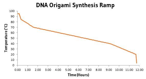
Synthesis Annealing - Samples were annealed in a Bio-Rad C1000™ Thermal Cycler using the following temperature settings: 95°C for 10 mins, then 94 to 86°C over 10 mins in 0.1°C steps, 85 to 70°C over 75 mins in 0.1°C steps, 70 to 40° in 450 mins in 0.1°C steps, 40 to 25°C in 150 mins in 0.1°C steps, then 10 mins at 20°C and stored at 4°C until use. Reaction volumes ranged from 20 to 150µl.
Agarose Gel
Agarose was dissolved to a final concentration of 1% (w/v) in 1x TAE (Biorad) and pre-stained with a drop of RedsafeTM nucleic acid staining solution. The samples were mixed with New Englands Biolabs 6x Gel loading dye and undergone electrophoresis for approximately 30 minutes at 120V. The gel was visualised under UV light post electrophoresis.
AFM
DNA origami structures were annealed with 5nM template and 10x staple excess. A drop of unpurified sample (5µl) was placed onto freshly cleaved mica surface and allowed to adsorb for 5 minutes, then AFM head was lowered until contact between the tip and the sample in solution was made. Imaging was performed on a Bioscope Catalyst™ Atomic Force Microscope (Bruker) using ScanAsyst and Peakforce Tapping mode in fluid, with SNL-A tips (Bruker). Spring constant was set to 0.58N/m, scan rate was 0.977Hz. Scan size was 1μm square with 512 samples/line.
Images were processed using Gwyddion software by first levelling data by mean plane subtraction, then correcting lines by matching height median, then setting the zero height andlevelling again by fitting a plane through three points. Each of the three points was chosen in an area free from structures and averaged over an 11-pixel radius.
EM
DNA origami samples were annealed as per the protocol above, drop cast onto carbon/formvar coated copper grids and given 5 minutes to adsorb. Excess sample was wicked off using filter paper. Grids were then negative stained for 2 minutes with 2% aqueous uranyl acetate. The excess stain was then wicked off using filter paper, and grids were dried overnight or until imaging. Imaging was performed on a Tecnai G2 20 Transmission Electron Microscope (FEI) in bright field mode at 200kV.
Scans which showed rectangular structures were assumed to show barrels side-on. From these scans, lengths and widths were measured in Gwyddion and averaged in Excel. Scans which showed ring-like structures were assumed to show barrels end-on. These were manually path-traced with Bezier curves and measured in Adobe Illustrator and averaged in Excel. The only structures measured in this case were those determined to be unambiguously closed.